Demystifying BMW Eccentric Shaft Sensor
Introduction
So I recently got into the impractical hobby of owning a relatively old and high mileage BMW. And apart of numerous leaks of various fluids I’m now having trouble with this weird and wonderful BMW’s Valvetronic “thing”.
And one of key components of it is the eccentric shaft sensor:
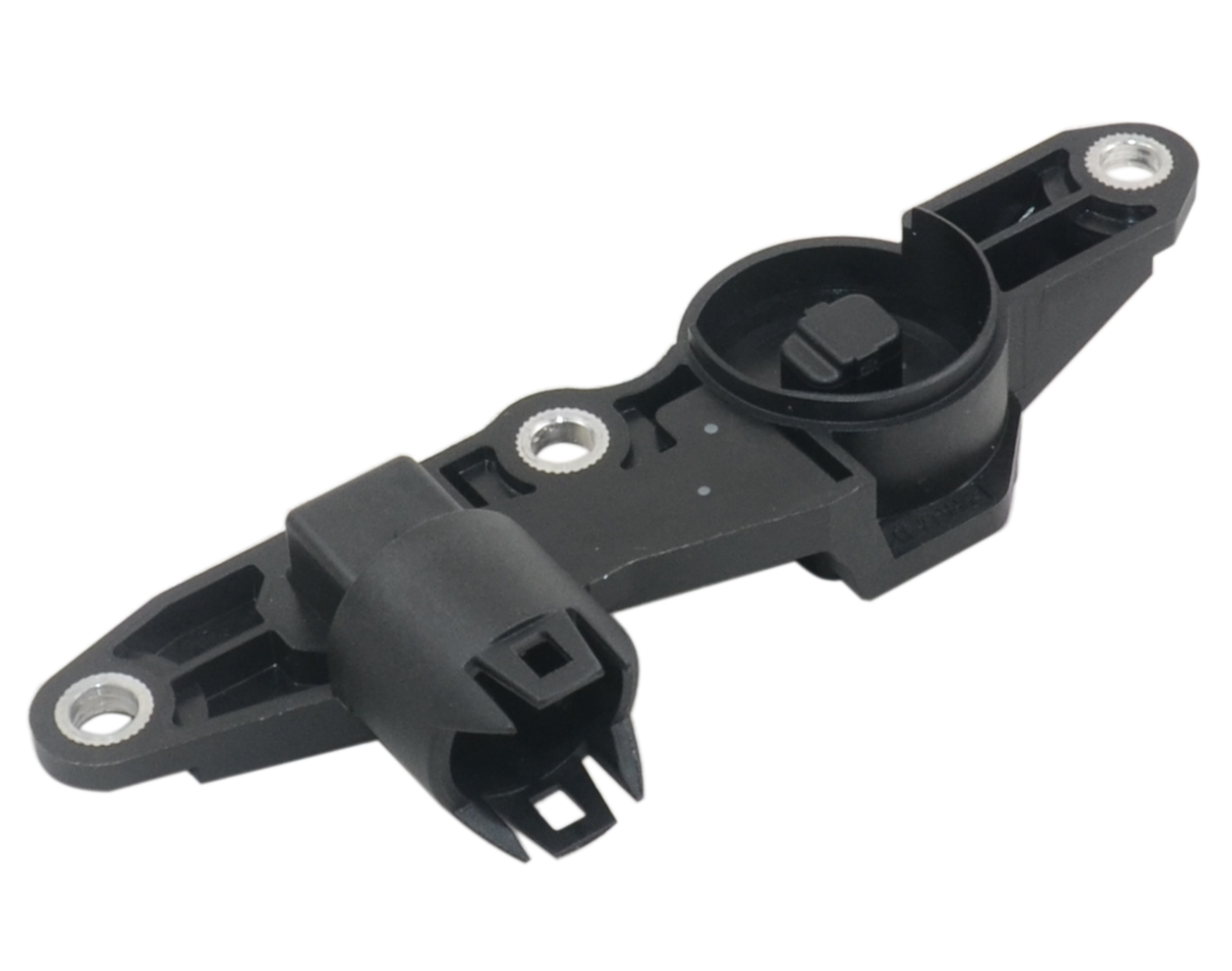
It’s located at the top of the engine and measures angle of this eccentric shaft. And the eccentric shaft itself is actuated by an electric motor. That motor is controlled by ECU which uses sensor to determine current angle of the shaft and turn it one way or the other. I honestly cannot explain what it does. For purpose of this article all we really need to know it’s a feedback for computer which is trying to put this eccentric shaft to one or another position.
And surprise surprise - the system is kinda unreliable. Both motor and sensor works in a harsh environment. Sensor bathes in hot oil which can reach temperatures higher than boiling water.
Interestingly my used car came with 2 spare sensors purchased while trying to resolve issues with Valvetronic. New OEM parts from BWM are often eye-watering expensive. In this case it’s ~460 euros. Aftermarket parts are much cheaper and can go for as low as 40 euros, but come with questionable reliability.
To my disappointment there isn’t really much information online about what’s exactly inside this sensor. Somewhat understandably most of the time it’s treated as this black magical box. So I thought it’s a good opportunity to tear one down and see if we can learn more about it.
The insides
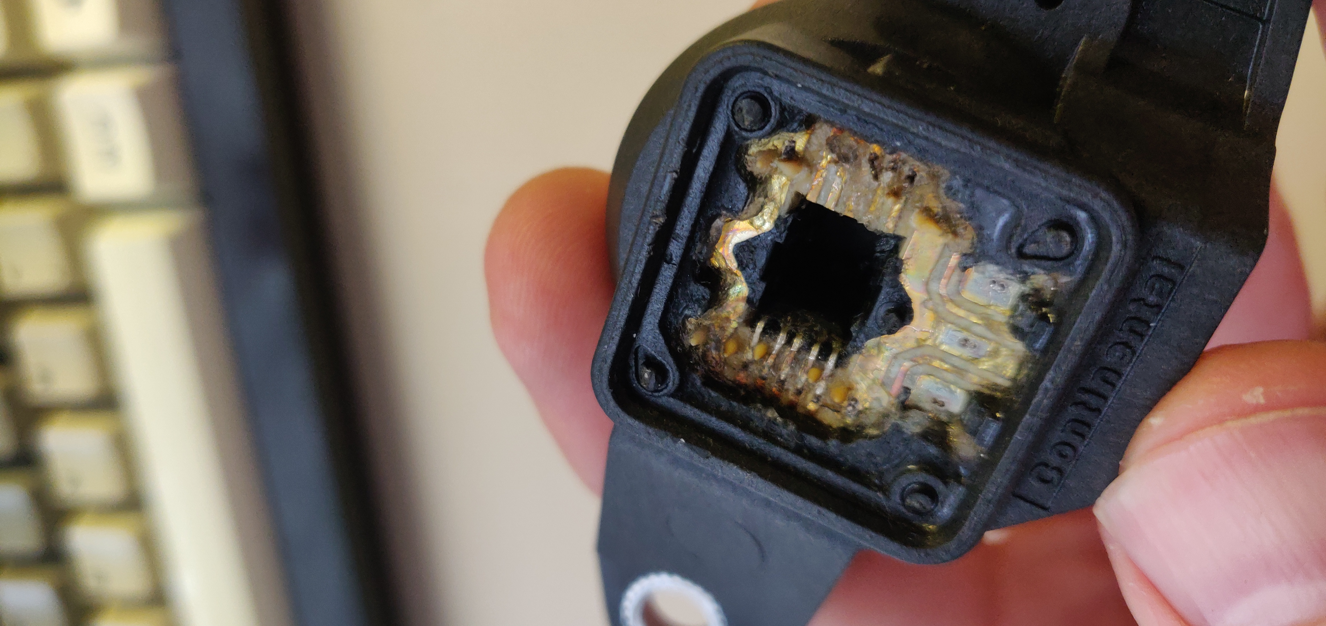
Back of the sensor has a metal cover:
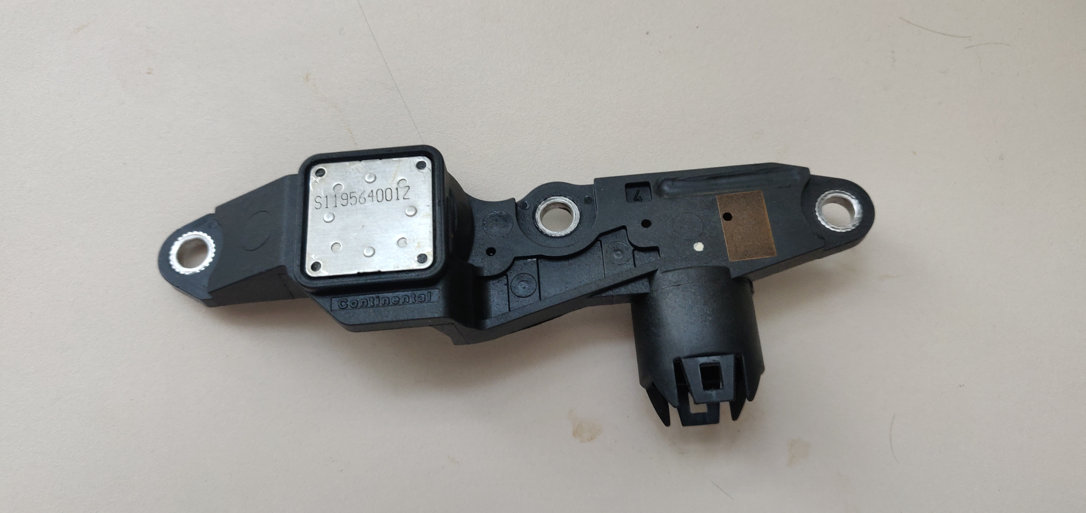
Underneath it:
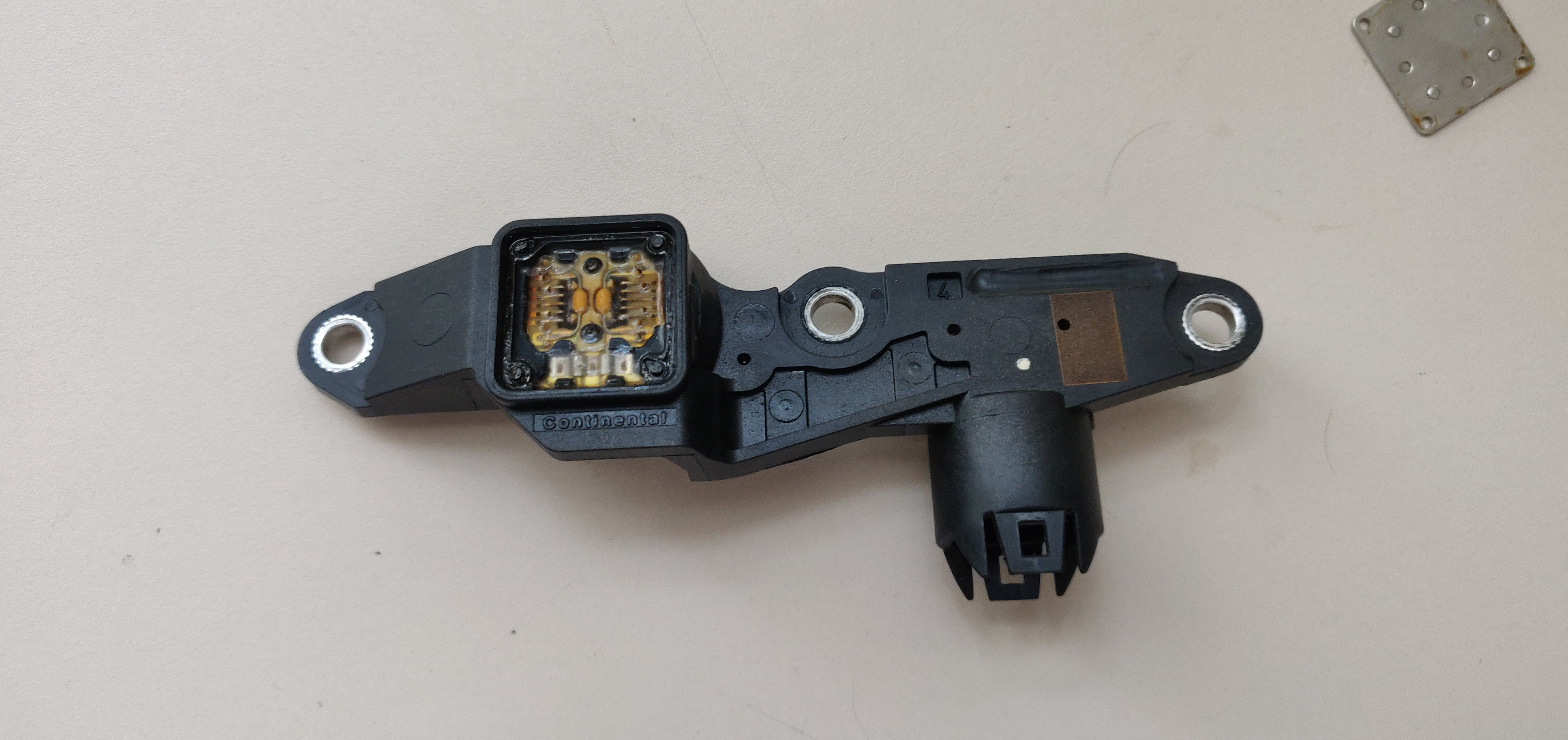
Internals are protected by some sort of jelly goo. Lucky for us it’s super soft and does not get in the way too much:
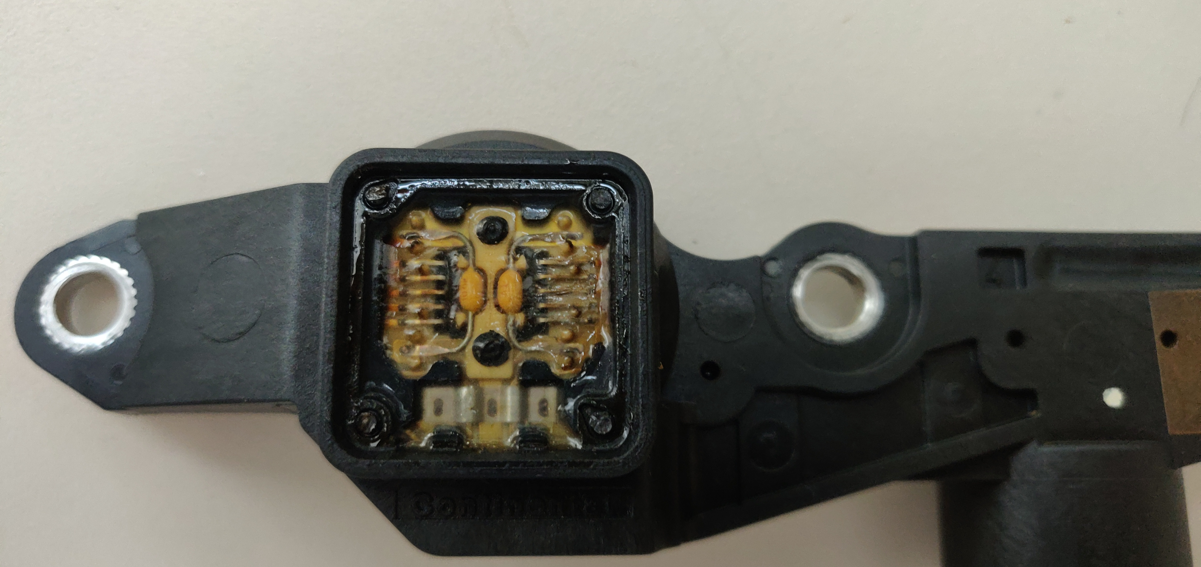
I tried bending those two capacitor looking yellow parts aside and they broke off quite easily. It does look like parts are spot welded instead of soldered to the board. Which makes sense given the silly high temperature these devices work in. Just to be sure I put it into component tester:
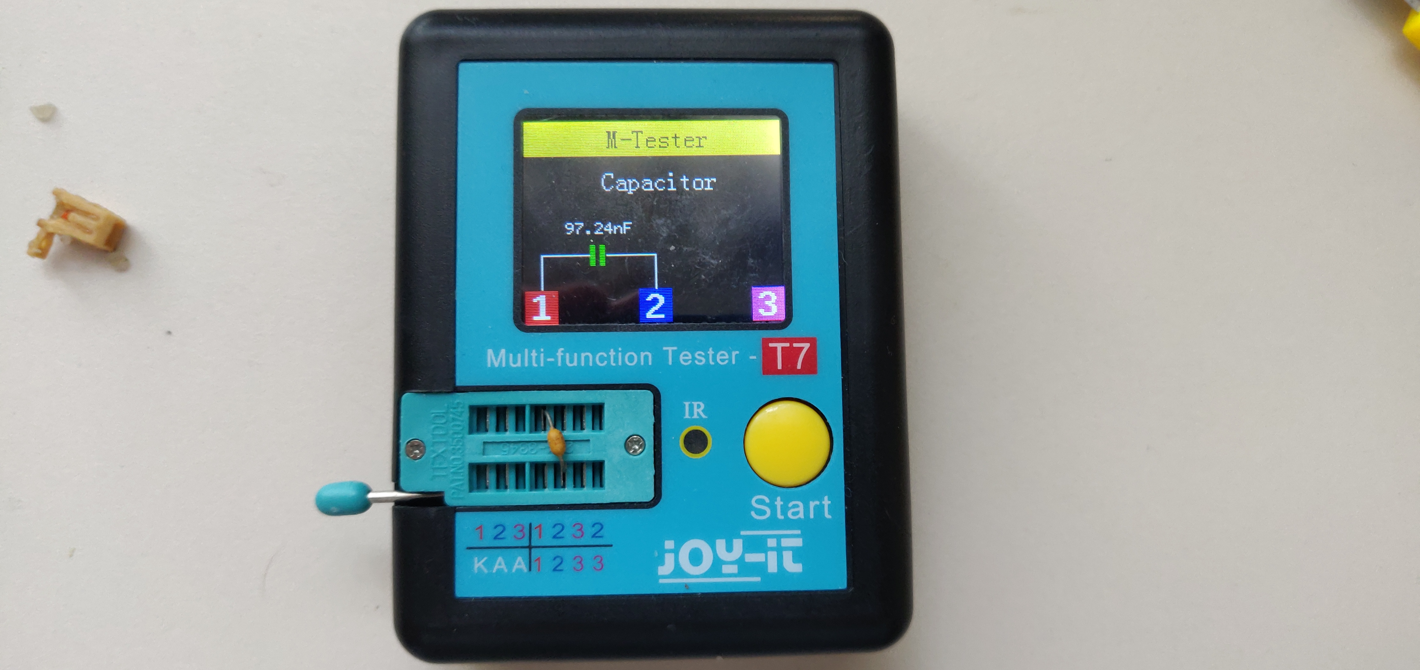
Both terminals where cap was connected also have continuity to the connector and chip pins. So yes - it’s 100nf power supply decoupling cap.
Pulled one of the chips. Aaaannd it has no markings whatsoever + I broke one of the pins:
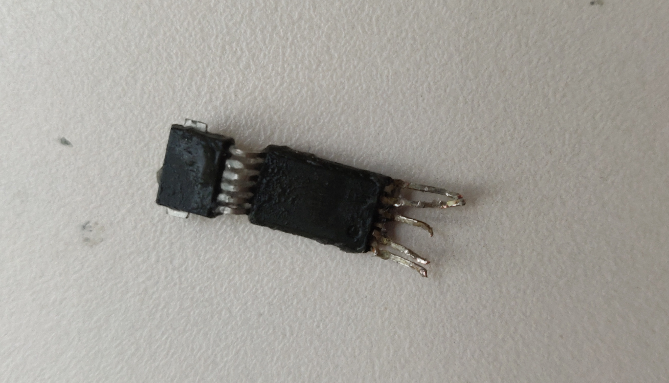
Good thing there’s a second one still inside:
Sensor chip has a rather unique appearance. And it so happens I recently watched a video about Tesla door handles which use a similarly looking sensor chip - KMA215 by NXP, but with different number of pins. So I looked it up on Digikey, browsed the same category and found KMA200 (mirror). It has 5 pins with matching GND and VCC (mentioned above - figured out from decoupling capacitor).
Notice how it’s two identical sensors in one package. ECU reads both and compares the values. If it does not match - a fault is reported.
From the datasheet I traced out this module connector pinout:
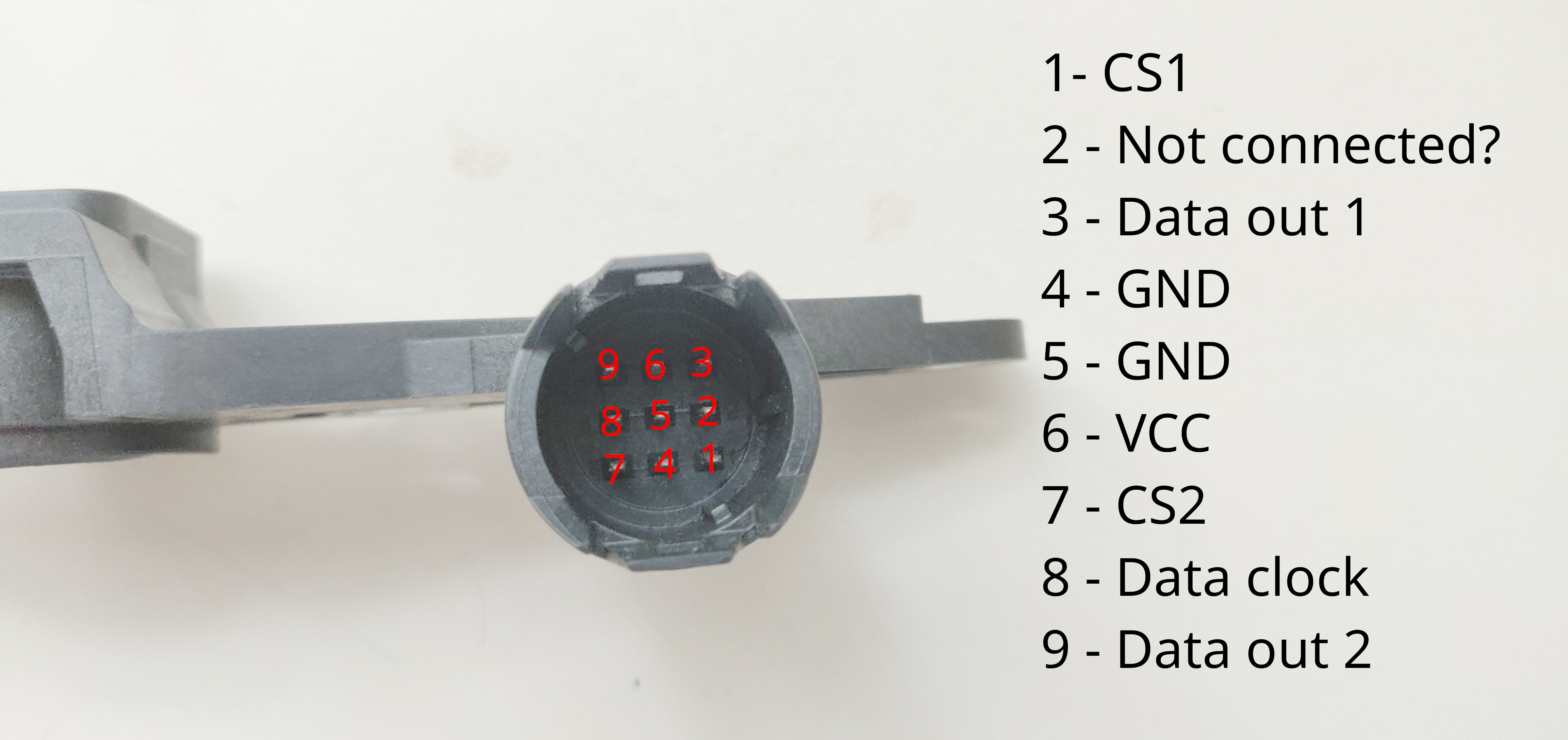
While I did butcher one side / chip, there was still one remaining to confirm my findings.
Hooked it up to Arduino SPI pins:
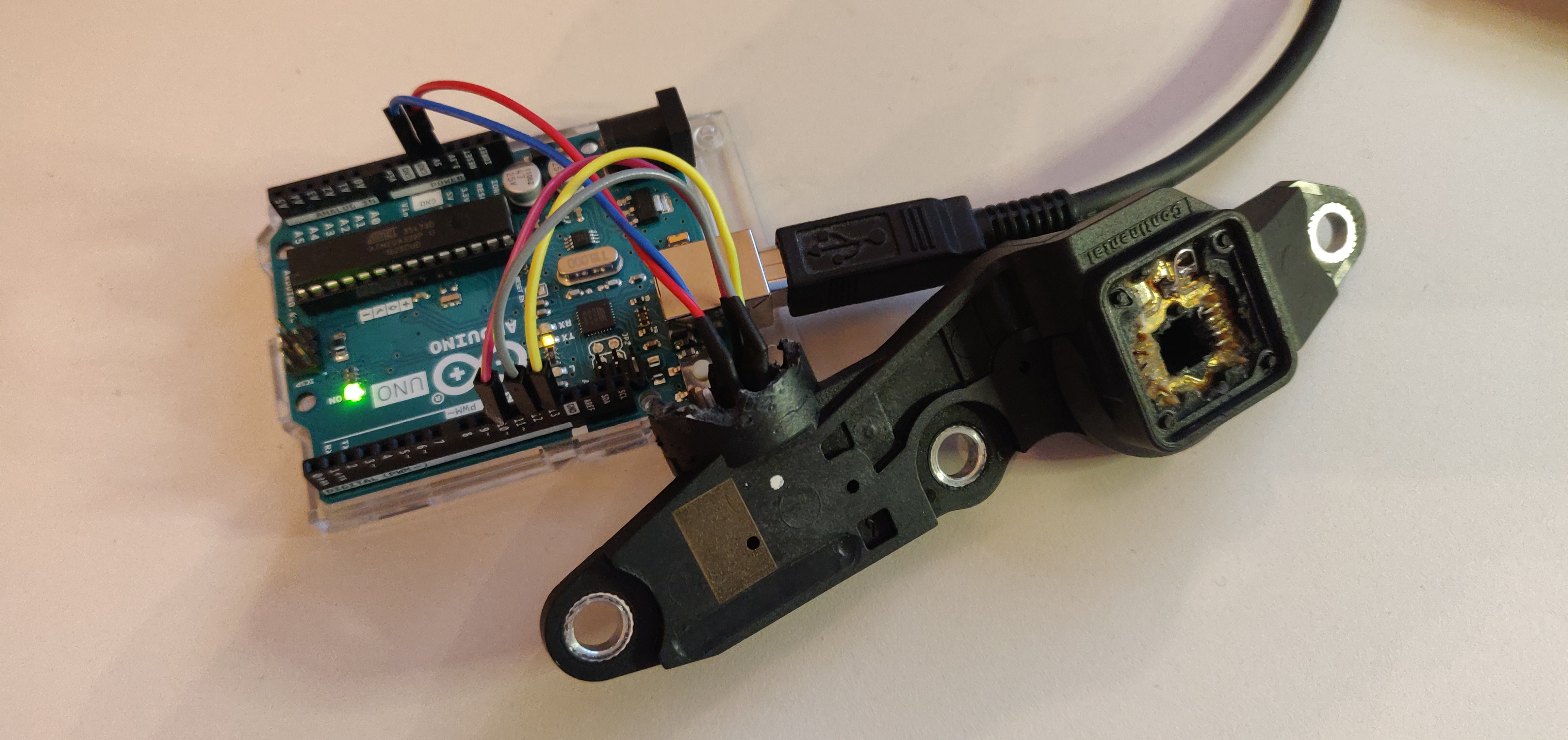
And got some data! At least the scope output showed something reasonable:
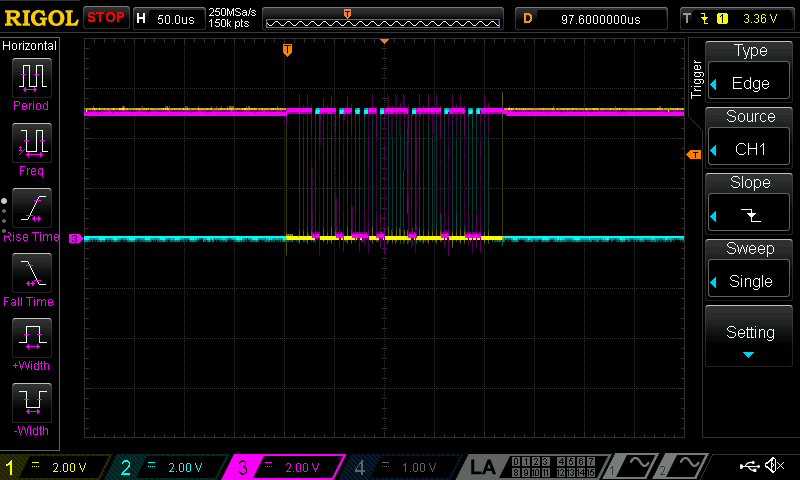
Screenshot is bit rubbish, but here we see: CS2 as yellow, DATA CLOCK as cyan and DATA OUT 2 as magenta trace. So we are getting some sort of digital data.
After some trial and error with datasheet provided “formulas” on how to interpret binary data I ended up with this Arduino sketch:
/*
  KMA200 sensor reading

 The circuit:
  * CS - to digital pin 10  (SS pin)
  * SDI - to digital pin 11 (MOSI pin)
  * CLK - to digital pin 13 (SCK pin)
*/

#include <SPI.h>

const int chipSelectPin = 10;

byte bytes[3];
byte byte0, byte1, byte2;

int temperature;
bool error;

SPISettings spiSettings;

void setup() {
  Serial.begin(115200);
  pinMode(chipSelectPin, OUTPUT);
  SPI.begin();
  spiSettings = SPISettings(100000, MSBFIRST, SPI_MODE0);
}

void loop() {
  SPI.beginTransaction(spiSettings);
  digitalWrite(chipSelectPin, LOW);

  SPI.transfer(&bytes, 3);
  byte0 = bytes[0];
  byte1 = bytes[1];
  byte2 = bytes[2];

  digitalWrite(chipSelectPin, HIGH);
  SPI.endTransaction();

  error = !!(~byte0 & 0b01000000);
  temperature = -50 + (~byte2 & 0b01111111)*2;
  unsigned int angleBits = ((~byte0 & 0b00111111) << 7) | (~byte1 & 0b01111111);
  float angle = angleBits * 0.022;

  Serial.print(angle);
  Serial.print("\t");
  Serial.print(temperature);
  Serial.print("C");
  Serial.print("\t");
  if (error) { Serial.print("error?"); }
  Serial.println();
  delay(100);
}
This does display a reasonable 20C temperature and rises if say heated with a hairdryer.
Angle readings also do mostly make sense. However I do not have a proper magnet to test it. Could be the reason why sensor often sets the error flag/bit.
Is this information of any use?
Probably not. But this was an interesting adventure nevertheless ¯\_(ツ)_/¯
One could write a Sigrok protocol decoder to read sensor “in place”, i.e. in a running engine. Although it’s not clear it’d be useful to anyone. Engine DME is usually good enough with error code reports to identify the fault.